This guide is an attempt to make sense of Holley EFI’s systems input/output functionality in their HP and Dominator ecu’s. If anything was missed, feel free to let us know, leave in a comment below, call or email us. If you have a question that wasn’t answered here, we’re happy to help through an email or phone call. In order to stay on the input/output topic, a better explanation of each function controlled mentioned in this guide will be done in seperate articles (Boost Control, Nitrous Control, Scramble, Datalogging, etc.)
DEFINITIONS
This is a list of the terms we’ll be referencing, and their definitions.
• 0-5 volt input – Sensor, transducer or other input with a 0 through 5 volt range. Example: Temp sensor that’s 0 Volts at 0 Degrees and 5 Volts at 100 Degrees with a provided range scale.
• 0-20 volt input – Same as the 0-5 Volt sensor but a 0-20 volt range
• Thermistor – Temperature-Variable resistor. A resistance based temperature sensor. Example: 2 wire coolant, and IAT sensors.
• Transducer – A sensor that converts pressure to an electrical signal/voltage. Example: 3 wire fuel pressure, oil pressure, nitrous pressure sensors.
• Map sensor – Manifold air pressure sensor – 1 Bar = 1 Atmosphere (14.7psi – which we breath every day at sea level) 1 Bar map sensor = (0.00 PSI Boost, 30 in/hg manifold vacuum) 2 Bar map sensor = (14.7 PSI Boost and 30 in/hg of manifold vacuum) etc.
• PWM (Pulse-Width-Modulated) – A DC supply voltage that is switched on and off at a given frequency for a modulated period of time (duty cycle). Example: A nitrous or boost control solenoid may be opened and closed rapidly (60-80+ times per second) using pulse width modulation to control wastegates, or nitrous output.
• Multi input – Can be configured as a 0-5V sensor input, 0-20v sensor input, thermistor temperature input, or high or low voltage input
• “Low” Ground switched – Switched grounding is (in our opionion) the better, and safer way of switching a device, solenoid, or relay. The device receives voltage (eg. 12 volt, 16 volt etc.) all the time, and ground is applied to power it. This is how most new cars and trucks power their accessories. (example: fuel pump received power on positive pin full time, ground is applied to turn it on) (example: nitrous solenoid receives power full time, ground is applied steadily or pulse width modulated to activate it)
• “High” Positive/Power switched – The opposite of ground switching above. Ground is always applied, and power is applied to activate. This is the old way of doing it, but preferred if you’d like to ground at the mounting point and run one wire.
• Inductive input – An oscillating AC voltage signal from a magnetic pickup sensor. Susceptible to noise and interferance.
• Flyback voltage – Large solenoids from nitrous kits, transbrake solenoids and others have a coil inside that acts like a small electric motor. When turned off, the closing action of the solenoid actually creates a large amount of voltage within the coil of the solenoid or relay, whatever is connected to that wire (typically the ECU input or output pin) will receive that voltage spike.
• IPU – Inductive/Magnetic pickup sensor ground. A dedicated ground for inductive sensors attached to any of the inputs on the ECU.
WARNING
Do not wire any input or output to a source that draws more than two amps. If the switched device exceeds two amps, you should connect the input or output from the ECU to the trigger side of a relay that’s used to power the device, and not directly to the device. When powering down, some solenoids actually generate a large amount of flyback voltage that is fed to the ECU, possibly damaging it. Consider using flyback voltage protection such as Holley 554-128 which can be found here.
THE BASICS
In another article (found here), we went over the basic functions and features of the Holley HP and Dominator systems which won’t be covered in this guide. While both ECU’s are very similar, most of the confusion comes from the quantity and type of inputs/outputs in each ecu. The two ECU’s do not hard code functions to a specific ECU pin. Doing so would waste an input or output if that feature isn’t used in a particular installation. The Holley software allows the user to specify what input/output pins are used for each function. Only the standard sensors and outputs are fixed and hard coded. They both have dedicated “fixed” inputs and outputs for the basic, common functions and sensors required for operation, the fixed inputs/outputs do not count towards the advertised input/output quantities.
The Holley HP
• Eight fixed fuel injector outputs
• Eight fixed ignition (EST) outputs (for use with individual coils, smart coils, LS coils, etc.)
• One fixed EST/Spout ignition output (if you’re outputting spark to a distributor module or an external ignition box) (use this or use the EST outputs for individual coils but not both)
• One fixed fuel pump output (additional fuel pumps will require use of an available output if you want to control it with parameters in the ECU
• CAN Low and CAN High outputs for dash display and accessory functions
• One fixed IAC Lo/Hi IAC motor output
• One fixed Crank sensor input
• Two fixed Knock sensor inputs
• One fixed Wideband sensor input
• One fixed Cam sensor input
• One fixed TPS sensor input
• One fixed Manifold air temp input
• One fixed Engine oil pressure input
• One fixed Coolant temp sensor input
• One fixed Manifold air pressure input (up to 5 bar)
• Four programmable high(+) or low(-) switched or PWM outputs
• Four fully configurable inputs
The Holley Dominator
• Twelve fixed fuel injector outputs
• Twelve fixed ignition (EST) outputs (for use with individual coils, smart coils, LS coils, etc.)
• One fixed EST/Spout ignition output (if you’re outputting spark to a distributor module or an external ignition box) (use this or use the EST outputs for individual coils but not both)
• One fixed fuel pump output (additional fuel pumps will require use of an available output if you want to control it with parameters in the ECU
• CAN Low and CAN High outputs for dash display and accessory functions
• One fixed IAC Lo/Hi IAC motor output
• One fixed Crank sensor input
• Two fixed Knock sensor inputs
• Two fixed Wideband sensor input
• One fixed Cam sensor input
• One fixed TPS sensor input
• One fixed Manifold air temp input
• One fixed Engine oil pressure input
• One fixed Coolant temp sensor input
• One fixed Manifold air pressure input (up to 7 bar)
• Thirteen “Multi Inputs” which can be used as 0-5v sensor input, 0-20v sensor input or thermistor temperature inputs
• Thirty 0-5v sensor inputs
• Four speed inputs which can be configured as inductive or digital (square wave)
• Twenty PWM (+) outputs which can be configured as switched (“H” +) or PWM (+)
• Sixteen PWM ground (-) outputs which can be configured as switched (“G” -) or PWM (-)
THE INPUTS
There are seven types of inputs that can be configured. You can connect the output from a sensor, switch, relay, transducer or you can use the output from a third party accessory, device or module wired to a Holley input to activate a Holley feature.
• “H” – Switched 12v (+) or “High Side” input – This input will be triggered when system voltage is applied. You can connect the 12v side output of a button, switch, or external device to this input to activate it. Minimum triggering voltage is 4.5v, and never exceed 24v.
• “G” – Switched ground (-) or “Low Side” input – This input is triggered when ground is applied to it. You can connect the ground side output of a button, switch, or external device to this input to activate it.
• “5” – 0-5v Sensor input – Any 0-5v sensor input such as TPS, MAP, Pressure Transducer, Shock Sensors, or any other type of sensor with a 5v output.
*Wire the signal output wire from a 0-5v sensor to the appropriate pin using the Holley wiring diagram. All 0-5v sensors require a 5 volt reference voltage and a sensor ground. Each Holley EFI connector that has 0-5v inputs has it’s own 5 volt reference voltage output and sensor ground. These need to be properly wired to each 0-5v sensor used. It is acceptable to have multiple sensors share the same 5 volt reference and sensor ground wires. Be sure to solder, heat shrink and secure wiring as poor connections will cause inaccurate and faulty sensor readings. Do not use 5 volt reference or ground sources from other controllers or power supplies, sensor accuracy will be comprimised.
• “2” – 0-20v Sensor input – Any sensor outputting a signal in the 0-20v range.
• “T” – Thermistor temperature input – Most coolant and air temp sensors that are a 2 wire thermistor design.
*Connect wiring to one side of the thermistor device, connect the other side of a thermistor device to a sensor ground input pin to the ECU (same input pins as a 0-5v sensor)
• “S” – Inductive Speed Input – Designed for an A/C voltage input from a speed/rotation sensor. A magnetic sensor is the most common sensor used. The minimum sensor output voltage to use this is 50mv.
*An inductive pickup is very susceptible to noise, and it’s highly advised to use a shielded/grounded cable. An inductive sensor has two wires, a positive, and a negative. Connect the positive lead to the “S” input pin that was pin mapped, and connect the negative side to an IPU ground.
• “F” – Frequency or digital speed input – Designed for digital voltage input from a speed/rotation sensor. Hall effect sensors are the most commong. Voltage output range can be 4.5v to 24v.
*A hall effect sensor has 3 wires – Power, Ground and Signal. Most sensors can be supplied with 12 volts, but some require a 5 volt reference. Check the requirements of your sensor before making any connections. Not typically required with a hall effect sensor, it is always advised to use a shielded and ground cable to wire them. You should be shielding all three wires.
• Signal – run the sensor signal wire to the pin mapped channel.
• Power – either supply with clean switched power, or if it’s being used for another purpose, you can power from Pin B20 in the J1B connector which is a clean 12 volt power source. If the sensor requires 5 volts, use a 5v reference wire.
• Ground – Best connected to an IPU (Inductive/Magnetic pickup) or sensor ground.
While the inputs can be programmed, mapped and configured to work almost any way you can imagine, below are a couple simple examples. There are of course, hundreds of other configurations for these inputs.
Switches Example: Wire the output of a toggle switch to a Holley input to change boost settings or activate the scramble function, change rev limiters, trigger the datalogger, etc.
Sensor Example: Wire the 0-5v output from a Pressure Transducer, TPS, MAP, etc. to datalog in the Holley datalogger or activate a function in the Holley software based on sensor output.
External Module Example: If you’re using a third party nitrous controller (for some reason) and you want to activate nitrous retard, you can wire the retard output trigger wire from the controller to the input on the Holley and configure the Holley to do what you want when it sees the trigger.
Thermistor Sensor Example: If you’d like to datalog or monitor temperatures from anything (transmission, differential, cylinder head temp, etc.)
Frequency or Inductive Speed Sensor Example: If you’d like to add a magnetic or hall effect sensor to the driveshaft, or wheels to log speed, or activate a function in the ECU, you would use the “F” input.
THE OUTPUTS
All PWM (pulse width modulated) and switched outputs from either ECU are rated at a maximum of 2 amps. If a device will draw more then 2 amps, a relay or solenoid must be used. If the output is PWM, do not use a standard “switching” relay, instead use a solid state relay that’s designed to be modulated. The “Hella” relay is pretty popular.
Both ECU’s have four types of outputs that can be configured. The list below goes over them, and their wiring recommendations. The designation on the pin map output list is given first, then the description.
• “H” – Switched 12 volt (+) or “High Side” output – will output whatever the current system voltage is (12 volts, 14 volts, 16 volts, etc.) If switched device is over 2 amps, wire this output to the power terminal on the switching side of the relay you’re using.
• “G” – Ground (-) or “Low Side” output – will output a ground trigger when activated. If switched device is over 2 amps, wire this output to the ground terminal on the switching side of the relay you’re using.
• “P+” – 12 volt pulse width modulated output – Outputs a (+) high side pulse width modulated output to control solid state relays, progressive nitrous solenoids, boost control valves, PWM IAC (idle air control) valves, or any other pulse width modulated devices.
• “P-” – Ground pulse width modulated output – Outputs a (-) low side pulse width modulated output to control solid state relays, progressive nitrous solenoids, boost control valves, PWM IAC (idle air control) valves, or any other pulse width modulated devices.
“H” Switched output example scenario: You can assign a function to any of the “H” outputs to trigger relays for fans, activate an external light, activate an external controller, etc. Anything you could switch with a button or switch can be done automatically by the ECU based on programming.
“G” Switched output example scenario: Same as the “H” switched example above, but ground is applied to activate instead of power.
“P+” Output example scenario: If you need to modulate a trans brake solenoid to roll forward instead of bumping, you can activate a “P+” output with a switch or button input. You can also use it for progressive nitrous control, boost control, and anything else you’d like to control with (+) pulse width modulation.
“P-” Output example scenario: Same as the “P+” switched example above, but modulated ground is applied instead of modulated power.
THE PIN MAP
The pin map is where you’ll go in the software to assign your inputs, outputs, change their functions, and switch them from “Switched” to “PWM”.
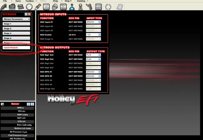
Some pin mapping definitions to help the reader follow along
• Function – A brief description of of a particular listed function
• Assigned ECU PIN – Shows which connector, and which pin in that connector that function is mapped to. If the pin isn’t mapped, it will display “NOT DEFINED”. Before the function will operate, it will need to be assigned to the ECU pin the device or relay is connected to.
• Input Type – This is where the user can choose whether an input or output is going to be “high” 12 volt (+) or “low” ground (-). Pulse width modulated outputs will display as (PWN+) or (PWM-) for high and low.
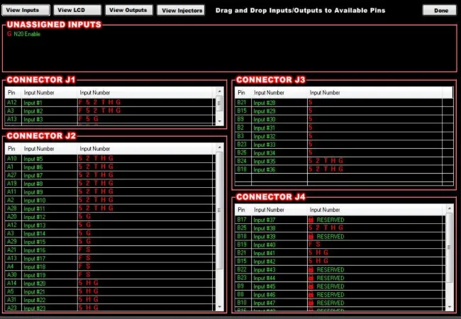
Pin mapping begins by creating and defining a new global folder (GF) and selecting which Individual Configuration Files (ICF) are to be used. If an ICF has an input or output that will need to be pin mapped, it will have an “Inputs/Outputs” tab (shown above) at the bottom of the window selections. Each inputs/outputs screen for a specific ICF will show all of the possible inputs and outputs that be be enabled and configured for that possible ICF. The ones that are enabled will have white and bold text. The ones that are not enabled will be grey and will not be editable.
Once the global folder is fully defined and the inputs/outputs are configured for your ICF’s, it’s time to use the actual pin map itself. You can find it in the center of the main menu bar, the small grey box “Pin Map”.
• View Inputs – Used to configure all input pins
• View LCD – Used to configure up to 10 switched inputs to be activated bt the optional 5.7″ touch screen LCD if being used.
• View Outputs – Used to configure all output pins
• View Injectors – Used to view what injectors are assigned. All of these are “fixed” and hard coded. If using for water/meth outputs, look at this screen to see what pins to wire your water/meth solenoids to.
At this point, all of the inputs and outputs you created in your previous ICF configuration steps should be shown in the “Unassigned Inputs” or “Unassigned Outputs” area. Each will have a symbol (letter or number) next to them to indicate the type of input or output that it is. [To keep from being repetitive, the definitions for all of these inputs/outputs are in the above sections of this guide] Next, you’ll drag and drop each input or output to an ECU pin that has the same symbol (it will not allow you to drop an incorrect type) Once this is finished, you’ll need to wire the inputs/outputs into the harness that you’ve assigned the pins to. Be sure you are careful when pinning a harness so that you select the intended pin locations.
THE CONNECTORS
The HP ECU has two main connectors:
• J1A – The first connector next to the USB connector is the “J1A” connector (34 pin). This connector is primarily an input connector. it contains all of the sensor inputs and wide band oxygen control.
• J1B – The second connector is the “J1B” connector (26 pin). This connector is the output connector. It has the 8 injector outputs, 8 EST DIS ignition outputs, 4 IAC outputs, and 4 user programmable outputs.

The HP ECU has four programmable inputs and four programmable outputs. When the software is configured for an HP ECU (under “toolbox and “preferences”) it will only show these four available inputs and ouputs. The physical wiring for these inputs/ouputs are in the harness (on every terminated harness) is located on an 8 pin, male metripack connector on the harness about 30″ from the ECU connectors. An adapter harness P/N 558-400 to plug into this can be found here, and is not included in Holley premade harnesses.
The Dominator ECU’s have programmable inputs and outputs on every connector. The picture below shows what connector relates to what pin map. Note that the letters “P” and “J” are interchanged in places for the connectors. They can be thought of as the same. The “P” refers to the male harness connector and the “J” refers to the mating female connector.
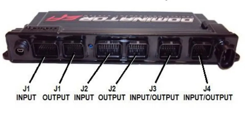
The Dominator ECU contains the same two main connectors as the HP ECU (J1A, J1B). The main wiring harnesses are identical between the two, meaning the Dominator ECU can be installed in place of an HP ECU. The Dominator has four additional connectors that the HP does not.
• J2A – An input connector for the second wideband sensor, and a variety of user programmable inputs.
• J2B – An output connector for the four additional injector drivers, the four additional ignition coil drivers, and a variety of user programmable outputs.
• J3 – This connector is intended for use by the drive-by-wire feature, it also contains a dedicated pin for the map selector switch p/n 558-407 found here, and a variety of user programmable inputs and outputs.
• J4 – This connector is intended for electronic, automatic transmission control. If an electronic transmission doesn’t need to be controlled, all of the pins in this connector (both inputs and outputs) will be available and open for use as user programmable options.
We stock most of these connectors, and they can be found in the “Electrical” section of our website. This guide will be amended at a later date (sooner then later) with the part numbers and links to the pins and plugs. The premade Holley EFI AUX harnesses can however be found in the wiring harnesses section found here.
WRAPPING UP
There are seperate instructional articles for each of the topics (boost control setup/wiring, nitrous systems setup/wiring, etc.) This guide was only meant to give you a basic understanding of how many inputs/outputs each system has while comparing, and some examples of what you can do with them. If we missed something, feel free to comment below, call us, send us an email, or stop by the retail store and yell at us in person, we can take it. Please consider sharing this article, we also sell everything mentioned in this article. Browse the site, if something you need isn’t shown, call us.